DMX accessories
DMX512
DMX512, often shortened to DMX, is a communications protocol used mainly to control stage lighting.DMX provides upto 512 control channels per data link (hence the 512 part of the name). Each of these 512 channels was originally intended to control lamp dimmer levels - you can think of it as 512 sliders on a lighting console connected to 512 light bulbs - each sliders position is sent over the data link as an 8-bit number having a value between 0 and 255. The value 0 corresponds to the light bulb being completely off while 255 corresponds to the light bulb being fully on.
With advances in lighting design it was a simple step to use the same 0-255 values to control the rotation of a gobo or colour wheel, the pan or tilt of a mirror head or the aperture of a lens.
The DMX protocol is very simple and robust, the data is transmitted continuously at upto 1000 times per second so if for some reason the data is not interpreted correctly the first time around, it will be re-sent a fraction of a second later.
-
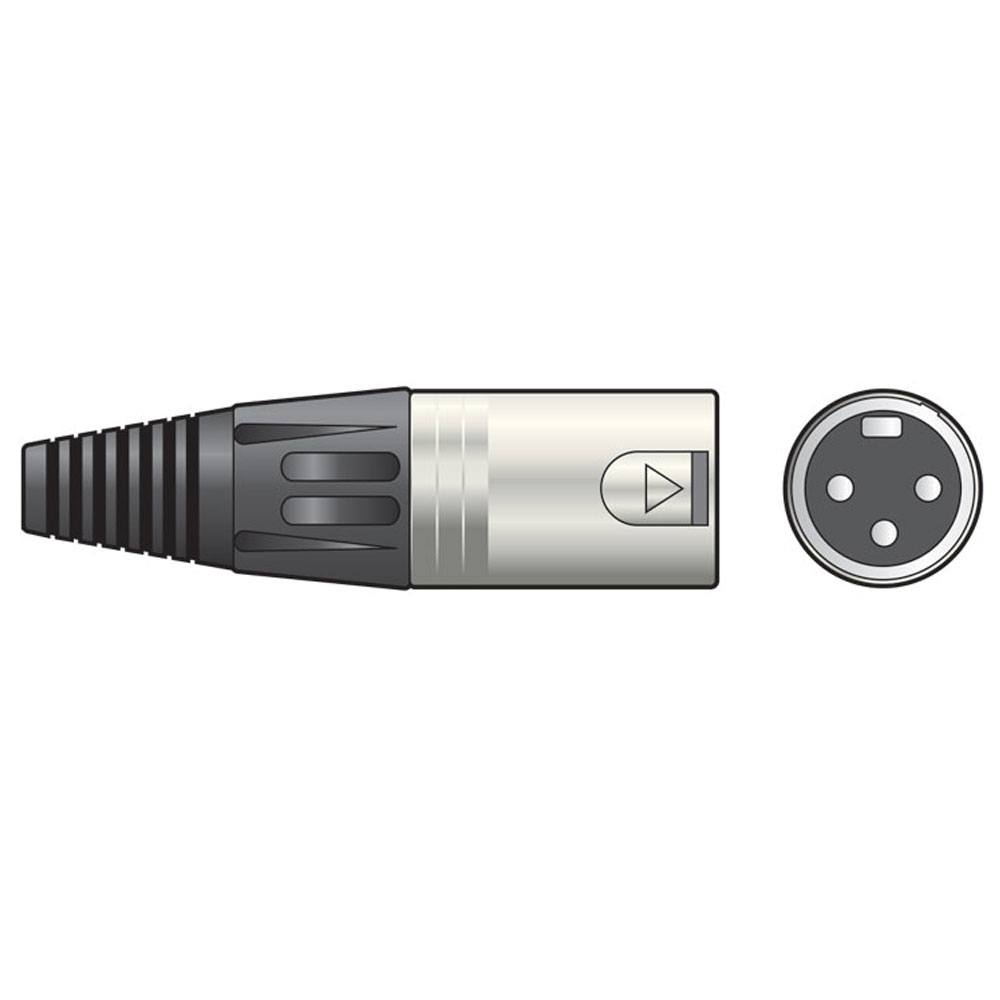
DMX terminator with 3-pin XLR connector
 £1.96
£1.96£2.69(£1.63 ex VAT)MX177924
End-connector/terminator for DMX-systems - 120 Ohms.
-
NEUTRIK 3-pin female XLR to 5-pin male XLR
 £10.22
£12.35(£8.52 ex VAT)MX993082
3-pin female XLR to 5-pin male XLR. For DMX lighting equipment.
DMX cables & terminators
Although DMX cables look like ordinary microphone cables, they are infact manufactured from special twisted pair cables that ensure the safe transmission of the DMX signals.
In a typical installation each effect is "daisy-chained" to the next, starting with the DMX controller and ending with a terminator - most DMX light effects have both a DMX in and a DMX out connection to facilitate this.
It is recommended to fit a 177.924 DMX loop terminator at the end of the DMX loop
Setting up
Each light in a DMX system is "daisy-chained" to the next using special DMX cables typically using 3-pin or 5-pin XLR connectors - each light has an input socket (XLR male) and output socket (XLR female).
A controller is fitted at one end of the chain and a 120 ohms resistor in the form of a terminator at the other. The terminator works by absorbing signal power which would otherwise be reflected back into the cable and degrade the data transmission, that said, it is possible to operate a small number of devices without a terminator.
|
|
3-pin XLR connections
1=GND, 2=DATA (-), 3=DATA (+) |

|
5-pin XLR connections
1=GND, 2=DATA (-), 3=DATA (+), 4=NOT USED, 5= NOT USED |
Each light in a DMX set up requires a number of channels to operate.
The first channel that a light effect uses is typically set using DIP switches on the unit, or in some cases a simple LED display and push buttons - you should refer to the manual of each effect for more details.
|
|
| DMX channel is set using DIP switches or through the LED display depending on the design of each unit. |